Servicing the Flushing Pump
Share
General
On Re-assembly always replace the rubber, leather and copper/asbcstos parts - all these components are provided in the cruising spares kits. Only apply semi-hardening jointing compound where specified.
Also take care to inspect the condition of the moving parts for undue wear (T-handle shaft ( or pump spindle) and gland nuts) as this may cause leakage even if the pump top seal is overhauled.
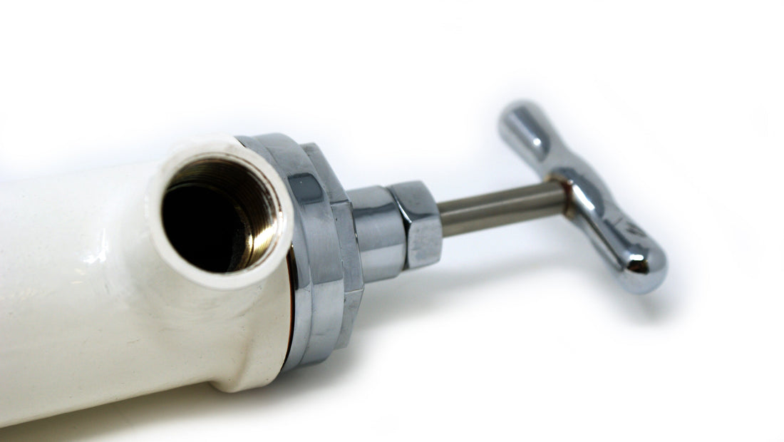
Removal of Pump Body
Use spanner C to disconnect the wheel control valve (11 or VE11) by unscrewing the nut (12 or VE12).
Remove the assembly bolt (2 bolts in the case of the minor model) at the base of the flushing pump unit. The flushing pump unit is now free for further dismantling.
Securing Pump Body in Further Operations
For further operations the flushing pump body must be prevented from turning. To prevent damaging the pump body use key H. This is held in a vice and locates in the wheel control valve spigot (12 or VE12) between two lugs and prevents the pump body from turning.
Removal of the Flushing Unit From Pump Body
The flushing pump top has a shallow octagonal top and it is recommended that spanner E is used to unscrew the top.
Examining and Replacing Rubber Bucket Washer
Hold the valve plug (24 or VE24) in a vice. Locate a screwdriver (or bar) through the bridge piece (23 or VE24).
This will allow removal of the bucket washer (25 or VE35). Replace the washer. Note: the tolerance on the bucket washers is oversized to allow for any wear on the cylinder. Therefore, it may be necessary to take a little of the material off the outer circumference - as evenly as possible - using a file or emery paper.
Servicing Flushing Unit - Pump Top Seal
To access the lip seal (83LS or VE83LS) in the pump top (81LS or VE81LS) or gland nut (82LS or VE82LS) the pump top and T-handle (13 or VE13) must be separated. Remove the bridge piece (23 or VE23) by holding the T-Handle (13 or VE13) in a soft jaw vice and then unscrewing the bridge piece (23 or VE23) by inserting a screwdriver or bar through its legs. The pump top is now free to be pulled off the T-handle (13 or VE13).
The lip seal (83LS or VE83LS) can be removed from the pump top (81LS or VE81LS) or gland nut (82LS or VE82LS) by using a sharp tool or piece of wire. It should be noted that whenever the T-handle is removed it is imperative the seal is replaced as damage to the seal is inevitable.
Replacement is best done through inserting the lip seal (with the flat tip of the seal facing upwards and the cup shape facing down towards the bridge piece (23 or VE23)) in the groove and using the flat end of a lead pencil or bic pen to ease it into place.
ASSEMBLE IN REVERSE ORDER
NOTE: Apply semi-hardening jointing compound to the threads on the pump top.
WARNING: when replacing the T-handle (13 or VE13) the initial threaded section should be very carefully screwed past the lip seal (83LS or VE83LS). If this is not done carefully the edge of the lip seal will be damaged and cause future leaking.
Overhauling Flushing Unit - Lower Valve Assembly
This should only be done in major services or if the flushing pump is not drawing well as it indicates excess wear and this poor seating between the lower valve (29A or VE29A) and lower valve housing (28 or VE28).
Ensure the pump body is held secure as described on page 42.
Remove the heavy valve assembly at the bottom end using spanner F.
Hold the lower valve housing (28 or VE28) in a bench vice. Remove the lower valve nut to dismantle the assembly.
Inspection of surfaces will indicate if there is excess wear, if so re-place the necessary components.
ASSEMBLE IN REVERSE ORDER.
NOTE: Apply semi-hardening jointing compound to the threads on the lower valve housing.