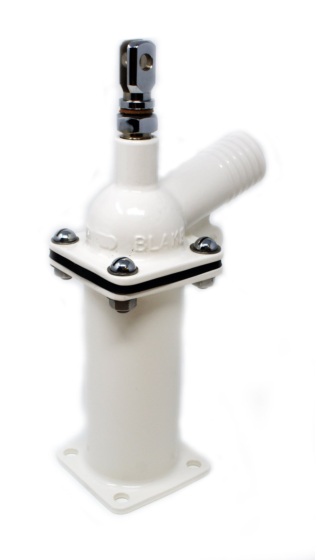
Servicing the Discharge Pump
Share
General
On re-assembly always replace the rubber, leather and copper/asbestos parts- all these components are provided with the Cruising spares kits (see section 4, TABLE B). Note: only use jointing (scaling) compounds where specified.
Also take care to inspect the condition of the moving parts for undue wear (discharge spindle and gland nuts) as this may cause leakage even if the pump top seal is serviced.
Removal of the Discharge Unit from Pump Body
- Remove both sets of star lock capped washers (27A) with a screw driver.
- Remove the crosspins (35 & 36). The handle (33) can then be removed.
- Remove the stirrup (34) from the outlet (76ALS) by undoing the nut and bolt (70).
- Remove the 4 bolts (71, 3 x 70) from the top of the cylinder (76ALS) and lift the discharge unit completely free from the cylinder.
Servicing the Discharge Unit
Replacement of weighted ball and rubber bucket washers
- Remove the centre weighted ball (52) which should be renewed if it is worn.
- Anchor the pump top by slipping the double lug (37) over a thin bar or spanner handle that is held in a bench vice. This will allow the unscrewing of the piston (48) - Use Key J.
- Remove the rubber bucket washers (51). Replace the bucket washers.
- Note that the tolerance on the bucket washers is oversize to allow for any wear on the cylinder, therefore it may be necessary to take a little of the material off the outer circumference - as evenly as possible - using a file or emery paper.
Pump top Seal:
To access the lip seal (78LS) in the pump top (76ALS) or gland nut (77LS) the pump top and discharge rod (39) must be separated. Hold the discharge rod (39) in a soft jaw vice to unscrew the double lug (37). Remove the leather washer (38). The discharge rod (39) can now be carefully withdrawn from the top (76ALS or 76A).
The lip seal (78LS) can be removed from the pump top (76ALS) or gland nut (77ls) by using a sharp tool pr piece of wire. It should be noted that whatever the discharge rod (39) is removed it is imperative the lip sea; (78LS) is replaced as damage to the lip seal is a definite possibility.
Replacement is best done by inserting the lip seal (with the flat top of the seal facing upwards and the cup shape facing down towards the hooded piston (48) into the groove and using the flat end of a lead pencil or ben or bie pen to ease it into place.
ASSEMBLE IN REVERSE ORDER
WARNING: When replacing the discharge rod (39) the initial threaded section should be very carefully screwed past the lip seal (78LS). If this is not done carefully the edge of the lip seal (78LS) will be damaged and may cause future leaking.
O-ring replacement
To replace the the O-RIng (78) in the pump top (76A) the pump top and discharge rod (39) must be separated as described for the lip seal type above.
To remove the O-Ring (78) first remove the gland nut (77) from the pump top (76A). Replace the O-Ring (78) with a new one.
ASSEMBLE IN REVERSE ORDER
WARNING: When replacing the discharge rod (39) the initial threaded section should be very carefully screwed past the O-Ring seal (78). If this is not done carefully the inside edge of the O-Ring seal will be damaged and may cause leaking.
Gland Packing
In these models the seal is made by winding graphite glad packing (72 or VE72 - supplied as standard in the cruising spares kit) around the shaft of discharge rod (39) just under the self adjusting gland nut (15 or VE15). There is no need to remove the discharge rod from the pump top to service the seal.
MODELS FROM 1962-1974 (self adjusting gland nut): Unscrew the self adjusting gland nut (65). Remove the old grease and gland packing. Put on some new grease - Blakes Seacock grease is recommended as this has the correct specifications - and wind one turn of gland packing at the top as shoulders. NOTE: this is a guide only, the objective should be to use enough gland packing so that the gland nut (63) takes up at least two threads on the pump top. After a bit of use it will be necessary to retighten but plenty of thread will be left for future adjustment.
MODELS PRE 1962 (old type gland nut): Unscrew the gland nut (41) from the pump top (40). Remove the old gland packing and neatly wind about 6-8 turns of new graphite gland packing onto the shaft of the discharge rod (39) and pack into the pump top (40). Screw down the gland nut (41) to bed down the packing. Again the objective should be to wind enough gland packing to allow the gland nut to take up at least two full turns (threads) in the pump top (40). This will leave plenty of room for future adjustment.
Servicing the Lower Valve
Unscrew the 4 assembly bolts at the base of the discharge cylinder (2). Lift the cylinder (2 clear of the syphon pipe (1A or 1MA).
The lower cylinder joint is a combined valve and joint (seal). The old type (54) design relied on a brass ball (53) for gravity closure. Current models use a superior clack type valve with a pressure lip for excellent sealing (84). This can be fitted to all ages of toilets and is supplied in the cruising spares kit.
Remove the clack valve assembly from the syphon pipe (1A or 1MA). Clean the syphon pipe thoroughly, checking that there are no obstructions. On replacement ensure the hinge of the clack valve is nearest the toilet pan (59A or V59A) so it opens in the correct way.